ASSIGNMENT ON COMPUTER NETWORKS
TOPICS:
SUBMITTED BY: DATE:12/08/2018
1.DIGITAL TRANSMISSION RAFAHNAH YASMEEN - MCA
2.CIRCUIT SWITCHED NETWORKS
DIGITAL TRANSMISSION
1.
DIGITAL TO DIGITAL CONVERSION
2.
ANALOG TO DIGITAL CONVERSION
3.
TRANSMISSION MODES
WHAT IS DIGITAL TRANSMISSION ?
Data tranmission is the transfer of data over a poini to point or multi-point communication channel.
Examples:
·
Copper
wires
·
Optical fibers
·
Wireless communication channels
·
Storage media
·
Computer buses
DIGITAL TO DIGITAL CONVERSION
We can represent digital data by using digital signals.
The conversion involves three techniques:
Ø
LINE CODING
Ø
BLOCK CODING
Ø
SCRAMBLING
Line
coding is always needed; block and
scrambling may or may not be needed.
LINE CODING:
Line coding is the process of converting digital data to digital signals. data in the form of text ,numbers, graphical image, audio, video, are stored in computer memory as sequences of bits.
§ Sender
–digital data are encoded into a signal;
§ Receiver
–the digital data are recreated by decoding the digital signal.
CHARACTERISTIC:
- SIGNAL ELEMENT VERSUS DATA ELEMENT
- DATA RATE VERSUS SIGNAL RATE
SIGNAL ELEMENT VS DATA ELEMENT :
- data element is the smallest entity that can represent a piece of information(a bit)
- A signal element is the shortest unit of a digital signal;
- data elements are what we need to send; signal elements what we can send.
- data elements are being carried; signal elements are the carriers.

DATA RATE VS SIGNAL RATE :
§
- bit rate and baud rate not always the same.
- the bit rate is the number of bits transmitted per sec,
- the baud rate is the number of signal units transmitted per sec
- one signal unit is able to represent one or more bits.
BAUD S=c*N*1/r
; N –data rate ,c – case factor, s-no
of signal element, r-previously define factor.
LINE CODING SCHEME
Digital line coding is a special coding system chosen to allow transmission to take place in a communications system .the chosen order or pattern of voltage used to represent binary digits on a transmission medium is called line coding.
CATEGORIES :
- Unipolar
- Polar
- Bi polar
- Multilevel
- Multi transition
UNIPOLAR:
All the signals level are on one side of the time axix, either above or below.
NRZ(NON RETURN TO ZERO):
In this scheme positive voltage defines bit 1 and the zero voltage defines bit 0.it is called NRZ because the signal does not return the middle of the bit
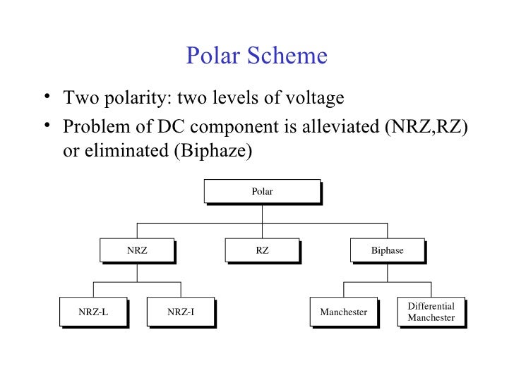
POLAR SCHEME:

In polar scheme voltage are on the both sides of the time
axix. that is voltage level 0 can be positive and the voltage level 1 can be
negative.
NRZ (non return to zero)
- In polar NRZ encoding ,we use to two levels of voltage amplitude. we can have two versions. NRZ:NRZL and NRZ-I.
- In NRZ-L, the level of the voltage determines the value of the bit.
- In NRZ-I, the change or lack of change in the level of the voltage determines the bit
- .if there is no change, the bits is 0 ; if there is a change , the bits 1.
BIPHASE: Manchester
and different Manchester
The idea of RZ(transition at the middle of bit)and the idea of NRZ-L are combined in to the Manchester scheme .in Manchester encoding , the duration if the bits is divided in to two halves .the voltage remains at one level during the first half and moves to the other level in the second half. the transition at the middle of the bit provides synchronisation.
Differential Manchester, on the other hand, combines the ideas of RZ and NRZ-.there is always a transition at the middle of the bit, but the bit values are determined at the beginning of the bit .if the next is 0,there is a transition; if next bit 1,there is none.
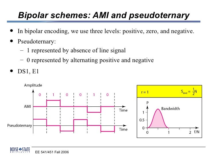
BIPOLAR SCHEME:

Bipolar encoding utilizes three voltage levels
:positive,negative and neutral(zero).zero used to represent binary 0 and b1
represent by alternating positive and negative voltages.
1.Alternate mark inversion(AMI):
o
AMI is a bipolar encoding system where zeo voltage represents binary 0 and alternating positive and negative voltages represents binary 1.with is line encoding it is the alternating voltages that determine the binary ones.
AMI is a bipolar encoding system where zeo voltage represents binary 0 and alternating positive and negative voltages represents binary 1.with is line encoding it is the alternating voltages that determine the binary ones.
Pseudomonas :
o
This encoding scheme is same as AMI, but alternating positive and negative pulses occur for binary 0 instead of binary 1.
This encoding scheme is same as AMI, but alternating positive and negative pulses occur for binary 0 instead of binary 1.
MULTILEVEL SCHEMES :
Abstract : 12B8T multilevel line coding scheme has been used as a alternative traditional line coding schemes e.g.4B3T, 8B6T schemes in digital to digital data conversion. Uni polar, polar, bipolar, multilevel, multi line are used in line coding.
2B1Q: two binary, one Quaternary, uses data patterns of size 2 and encodes the 2 bit pattern as one signal element belonging to a 4 level signal.
8B6T:eight binary, six ternary .this code is used to 100BASE-4Tcable

MULTILINE TRANSMISSION :MLT-3
It uses 3 levels(+v,0,-v)and three transition rules to move between the levels.
v
If the next bit is 0,there is no transition.
v
If the next bit is 1 and the current level is
not 0,the next level is 0.
v
If the next bit is 1 and the current level is
0,the next level is the opposite of the last nonzero level.
BLOCK CODING:
The decoder uses the redundant symbols to detect and possibly correct whatever errors occurred during transmission…block coding techniques map a fixed number of message symbols to a fixed number of code symbols. a block coder treats each block of data independently and is a memory less device.
4B/5B: The four binary/five binary coding schemes was
designed to be used in combination with NRZ-I

8B/10B:eight binary/ten binary encoding is similar to 4B/5B
encoding .

SCRAMBLING:
Scrambling is a technique that does not increase the number of bits and does provide synchronisation.
Ø
B8ZS
Ø
HD83
B8ZS: BIPOLAR WITH 8 ZERO SUBSTITUTION:
It is commonly used in north America .eight consecutive zero level voltages are replaced by the sequences 000VB0VB.
V-violation-bipolar,
HD83:HIGH DENSITY BIPOLAR 3 ZERO:
It is used outside of north America .which is more consecutive than B8ZS,4 consecutive zero level voltages are replaced with a sequences of 000V or B00V.
TWO RULES FOLLWES:
1.if the number of nonzero pulse after the last substitution is odd,000V nonzero even.
2. if the number of nonzero pulse after the last
substitution is odd,B00V nonzero even.
ANALOG TO DIGITAL
CONVERSION:
A device that converts analog signals to digital signals. analog information is transmitted by modulating a continuous transmission signal by amplifying a signal strength or varying its frequency to add or take away data it describes two techniques:
1.
PULSE CODE MODULATION
2.
DELTA MODULATION
PULSE CODE MODULATION:
The most common technique to change an analog signal to digital data(digitisation)is called pulse code modulation. it has three process:
- The analog signal is sampled.
- The sampled signal is quantized
- The quantized values are encoded as streams of bits.
Sampling:
The analog signal is sampled every TsS, where Ts is the sample interval or period. the inverse of sampling interval is called sampling rate or sampling frequency. denoted by fs.
THREE sampling methods:
o Ideal-pulses
from the analog signal are sampled, cannot
easily implemented.
o Natural
–a high speed switch is turned for only
the small period of time when sampling occurs.
Flat
top-common method called, sample and
hold, creates flattop samples by using circuit.
Sampling sometimes refer to PAM.
SAMPLING RATE:
What are the restrictions 0n Ts? Answered by nyquist.
NYQUIST THEOREM-to reproduce the original analog signal, one necessary condition is that the sampling rate be at least twice the highest rate in the original signal.
QUANTIZATION:
The set of amplitudes can be infinite with non integral values between the two limits .this value cannot used in the encoding process. the following steps are in quantization:
- We assume that the original analog signal has instantaneous amplitudes between Vmin and Vmax
- We divide the range integral L zones, each height delta. delta=Vmax -Vmin/L.
- We assign quantized values 0f 0 to L-1 to the mid point zone.
- We approximate the value of the sample amplitude to the quantized values.
ENCODING
That the number
of bits for each sampled is determine from the no of quantization levels.
Bit rate=sampling rate*no of bits per
sample=fs*nb
ORIGINAL SIGNAL RECOVERY:
ORIGINAL SIGNAL RECOVERY:
It requires pcm . it uses circuitry to convert the code words in to a pulse that holds the amplitude.
DELTA MODULATION:
This technique have bee developed to reduce the complexity of PCM. the simplest is delta modulation. pcm find the value; DM finds the change from the previous sample.
·
Modulator
·
Demodulator
·
Adaptive DM
·
Quantization error
MODULATOR:
The modulator is used at the sender site to create a stream of bits from an analog signal. the process records the small positive or negative changes called delta. delta is positive it records 1,negative it records 0.
DEMODULATOR:
The dm takes the digital data and using the staircase maker and the delay unit, creates a analog signal .
ADAPTIVE DM:
In adaptive DM ,the value of delta changes according to the amplitude of the analog signal.
QUANTIZATION error:
It is always introduced in the process. the QE of DM is much less than that for PCM.
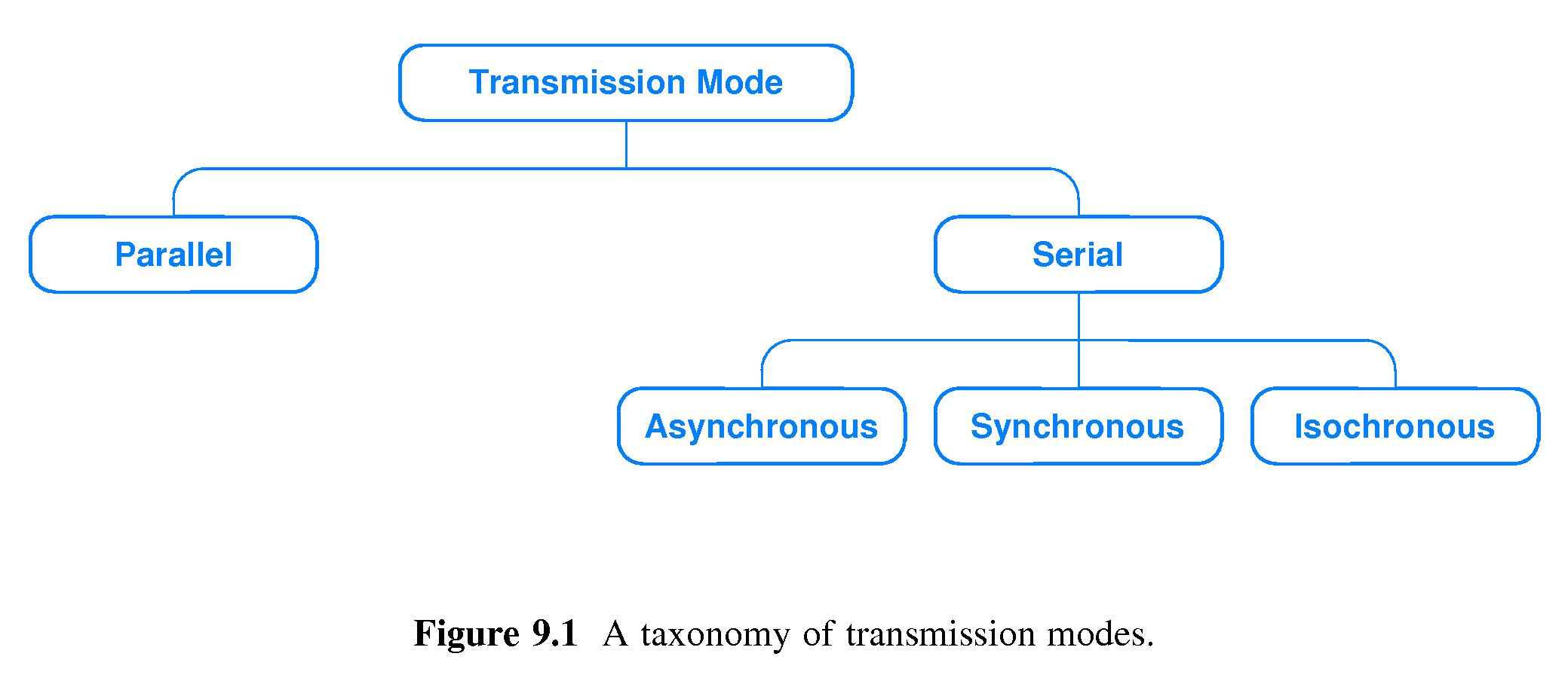
TRANSMISSION MODES:
Transmission of data from one device to another.
 |
|
Parallel transmission :
In parallel transmission ,all the bits of data are transmitted simultaneously on separate communication lines.
Advantages :
It is speed way of transmitting data as multiple bits are transmitted simultaneously
with a single clock pulse.
Disadvantages :
Its costly method and it requires n lines to transmit n bits at the same
time.
Serial transmission :
In serial transmission ,the various bits of data are transmitted
serially one after the other.

It is used for high speed communication between computers.
ASynchronous transmission:
it is possible to transmit signals from sources having different bit rates.
advantages :
use of single communication lines reduce the transmission line cost by the factor of n as compared to parallel.
Disadvantage: This method is slower.
ISynchronous :
It is provides synchronised for the entire stream of bits must.in other words ,it guarantees That the data arrive at a fixed rate.
CIRCUIT SWITCHED NETWORKS:
A CIRCUIT SWITCHED NETWORKS consists of a set of switches connected by physical links.a connection between two stations is a dedicated path made of one or more links.each connection uses only one dedicated channel on each link.each link is normally divided n channels by using Frequency Division Multiplexing or Time Division Multiplexing.
we need to emphasize several points:
- circuit switching takes place at the physical layer.
- before starting communication, the stations must make a reservation for the resources to be used during the communication. these resources, such as channels , switch buffers , switch processing time and switch input, output ports,he must remain dedicated during the entire duration of data transfer until tear down phase.
- data transfer between the two stations are not packetized.the data are a continuous flow sent by the destination station,although there may be periods of silence.
- there is no addressing involved during data transfer.the switches route the data based on their occupied band or time slot.there is end to end addressing used during the setup phase.
ADVANTAGE OF CIRCUIT SWITCHING:
- since a circuit is dedicated to data transmission there is no interference and no sharing of data.
- the full bandwidth of the channel is guranteed for the duration of the call.
DISADVANTAGE :
- takes a relatively long time to setup the circuit.
- the channel may not be utilized to its maximum.
- inflexible.
THREE PHASES:
- setup phase
- data transfer phase
- teardown phase
CONNECTION SETUP PHASE:
a physical connection established during the setup phase and the is broken during the teardown phase.
- before the two system can communicate a dedicated circuit must be established.it means creating dedicated channels between the switches.
- for ex:when system A needs to connect to system M,its send a setup request to switch1.this is address of system M.
- switch 1 finds a channel between itself and IV.
- switch 1 sends the request to switch IV.switch IV finds a dedicated channel betwwen itself and switch III.
- switch III informs system M that system A wants to communicate.
- system M sends an replay in the opposite direction system A.once received connection is established.
- end to end addressing is required for creating a connection between the two end system.
- address of the computer A and M.
DATA TRANSFER PHASE:
TEAR DOWN PHASE:
when one of the system needs to disconnect ,a signal is sent to each switch to release the resources.
EFFICIENCY:
circuit switched networks are not as efficient as packet and message switched networks. a channel is a resource and it is allocated during the entire duration of the connection.these resources are not available to other systems.
DELAY:
the total delay is due to the time needed to create a connection ,transfer data,and disconnect the circuit.the delay caused by the setup is the sum of
(i)propagation time of the source computer request,
(ii)request signal transfer time
(iii)propagation time of the reply from the destination to source
(iv)signal transfer time of the replay.
the delay due to transfer is the sum of two parts:
- propagation time and
- data transfer time.

